DIY Mixbox
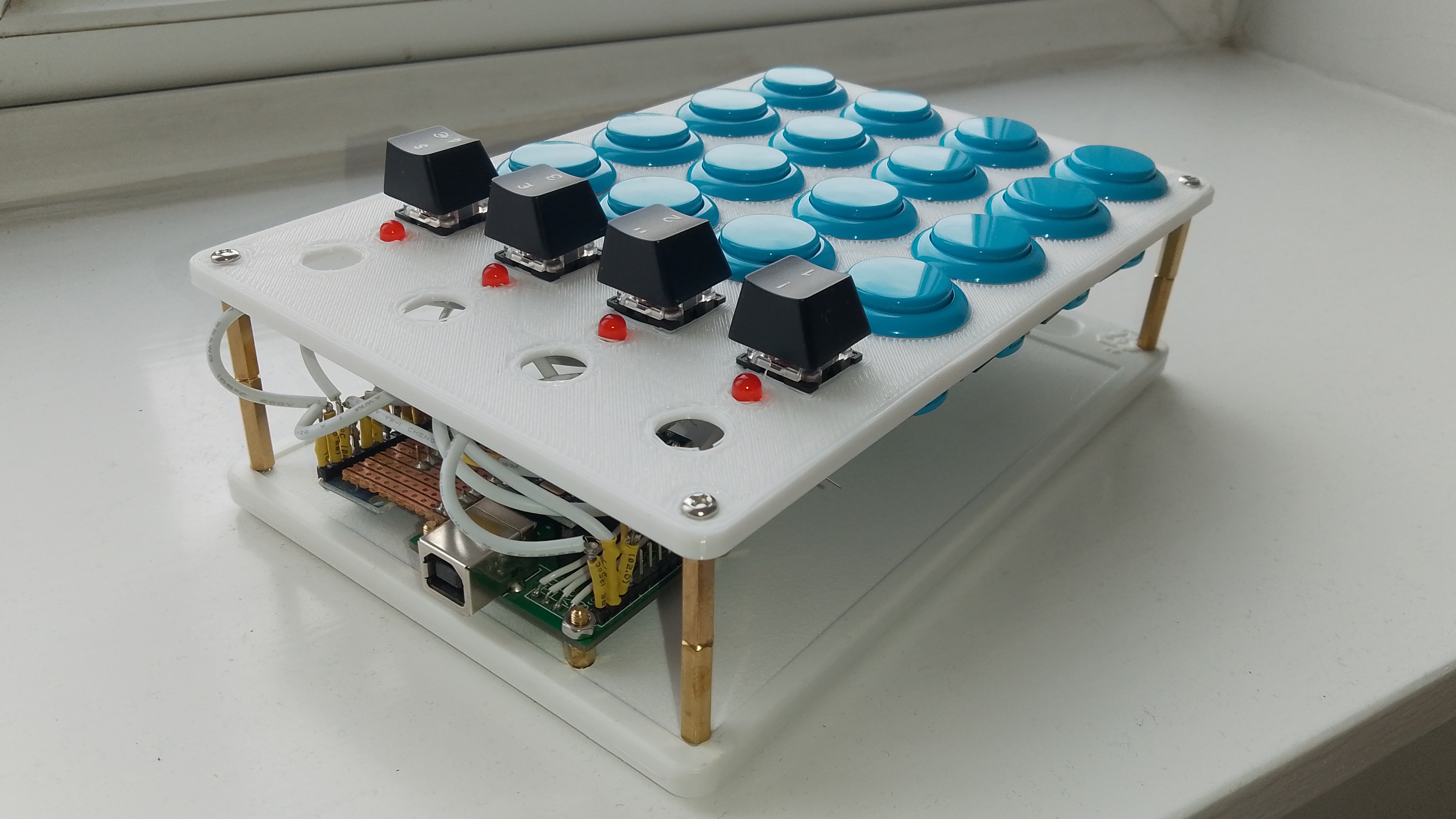
This is my DIY portable version of a Mixbox
UPDATE: Files are now available here on Thingiverse
The Mixbox is a controller designed for playing fighting games such as Street Fighter or Mortal Kombat. It is intended to combine the precision of using a keyboard with the ease of use of a fight stick. Since fighting games tend to rely on players being able to accurately move the joystick, in particular to make diagonal moves, this can be easier using a keyboard where this just requires a button press. However, keyboards can be uncomfortable for gaming and have a large number of extra buttons (for typing - doh!) which are a distraction when you need to remember exactly which ones to press. Hence, the Mixbox, which uses keys for the direction controls and standard arcade buttons for the punch/kick buttons.
I designed my version of the Mixbox to be a smaller portable version, as I’m already working on a large variant, The Hit Box, for home use. That one needs a bit more work before it is ready as the first prototype turned out a little flimsy and difficult to assemble.
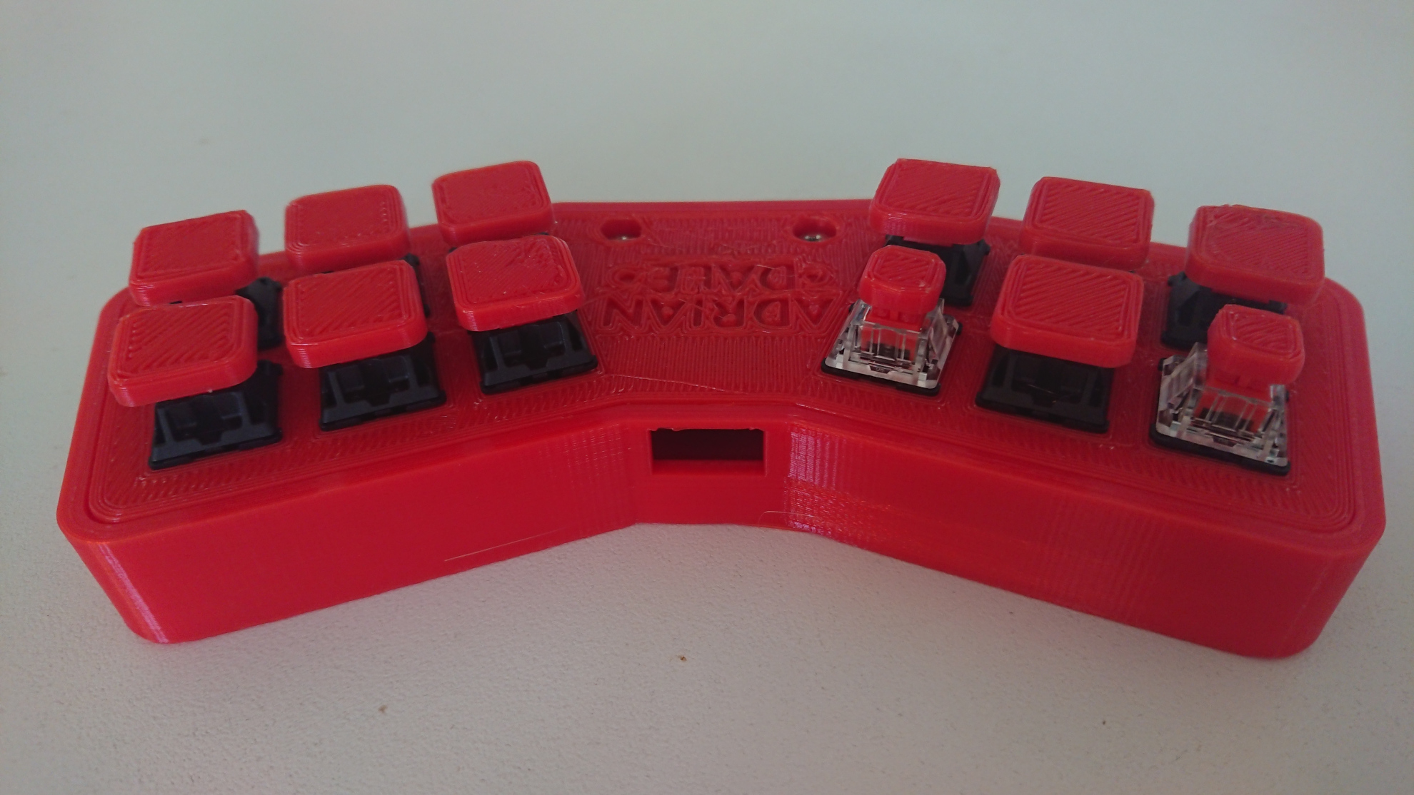
My portable Mixbox uses Cherry MX Red keyboard switches for all of the buttons, two of which are cheaper clone versions of the Cherry switches, for the less frequently used Back and Menu buttons.
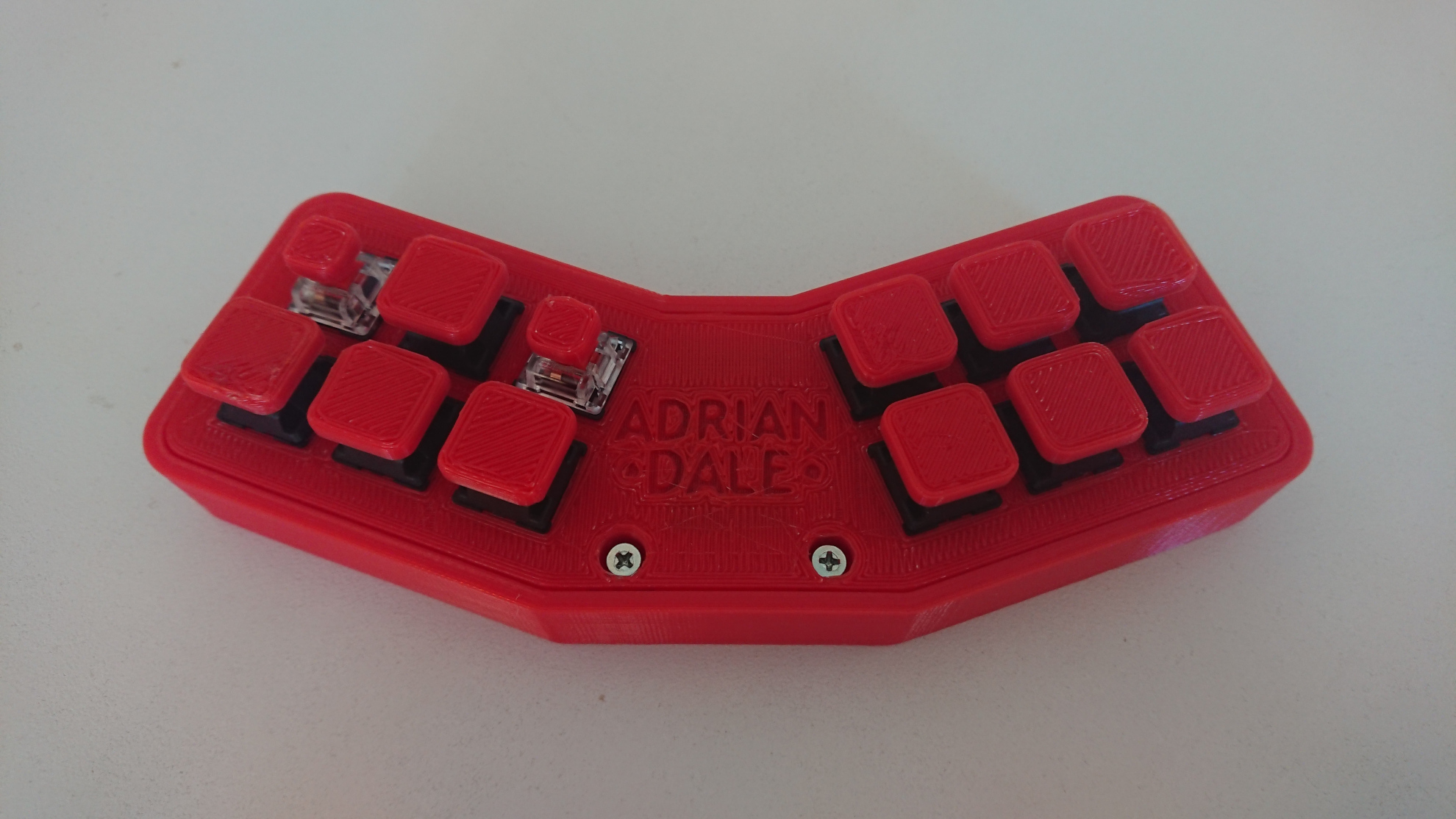
I used AutoDesk Fusion 360 to design the case, and the button keycaps. These printed on my 3D printer. I had to design the case carefully to make sure it fit within the print area available on my printer. I’ve given it the slightly odd looking angled design so that the player doesn’t have to bend their wrists so much to press the buttons. This allows the sets of buttons to be closer together and gives the case a smaller footprint.
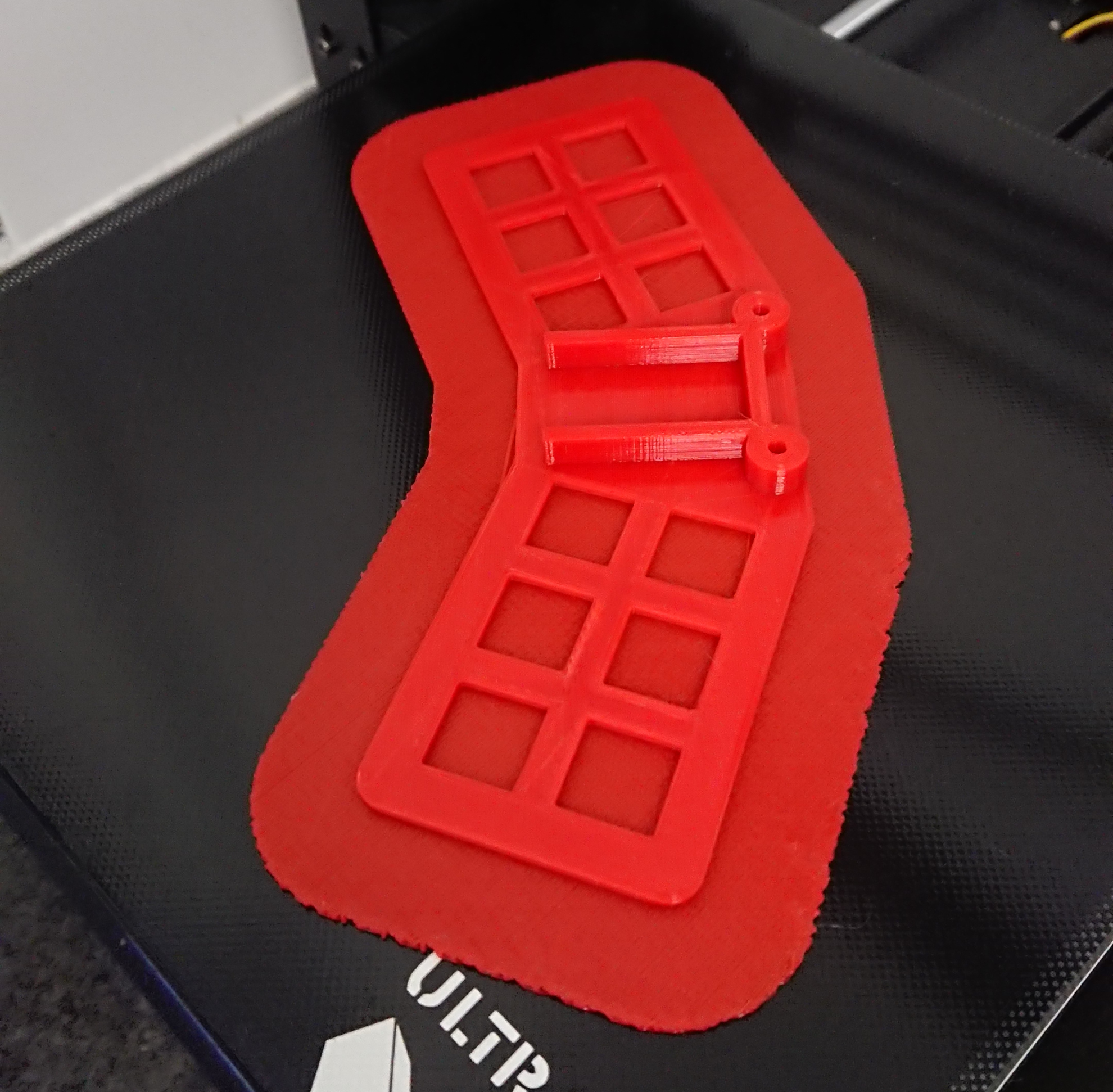
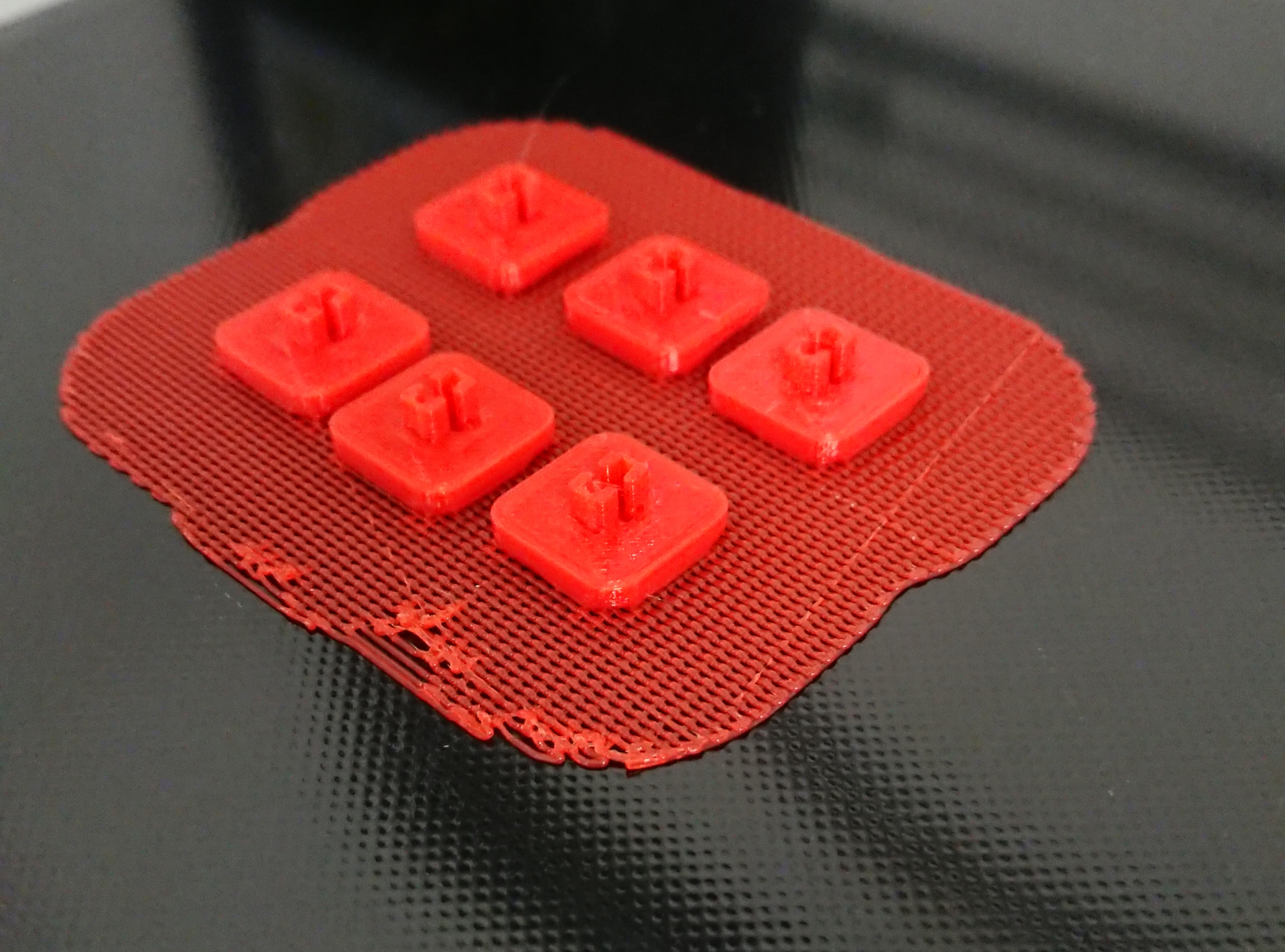
The keyswitches snap into place through square holes in the top of the case. The control unit for the controller is hot-glued to the underside of the lid of the case. The case and lid are held together using screws which go through captive nuts in the case. The keycaps are superglued to the key switch stems. I printed slightly smaller keycaps for the Back and Menu buttons to lessen the chances of them being pressed accidentally. Ideally, I think they ought to go on the side of the case, but I wanted all of the buttons attached to the same piece of the case to make the wiring easier. Finally, I added my name to the lid of the case as a finishing touch.
I had to tape over the LEDs on the control unit with electrical tape, as they were shining through the plastic casing. It could have been a cool effect, but it wasn’t evenly illuminating my embossed name. I may remove my name in a future revision, as it means I can’t really share the STL files for the project.
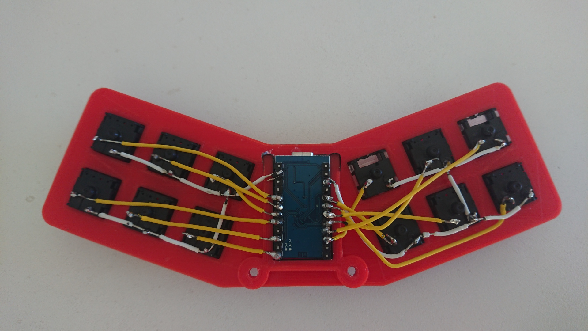
The control unit is an Arduino Pro Micro. I followed these instructions to turn it into an Xbox 360 compatible controller. For my earlier joystick project I bought a control board from ebay, but I found that in some games (eg Mortal Kombat 11, that I wanted to play) it doesn’t act the same as an Xbox controller. Therefore I preferred to program my own controller. This also allows me to have buttons to act as the analog triggers, although in this design I haven’t done that as I only have six action buttons available.
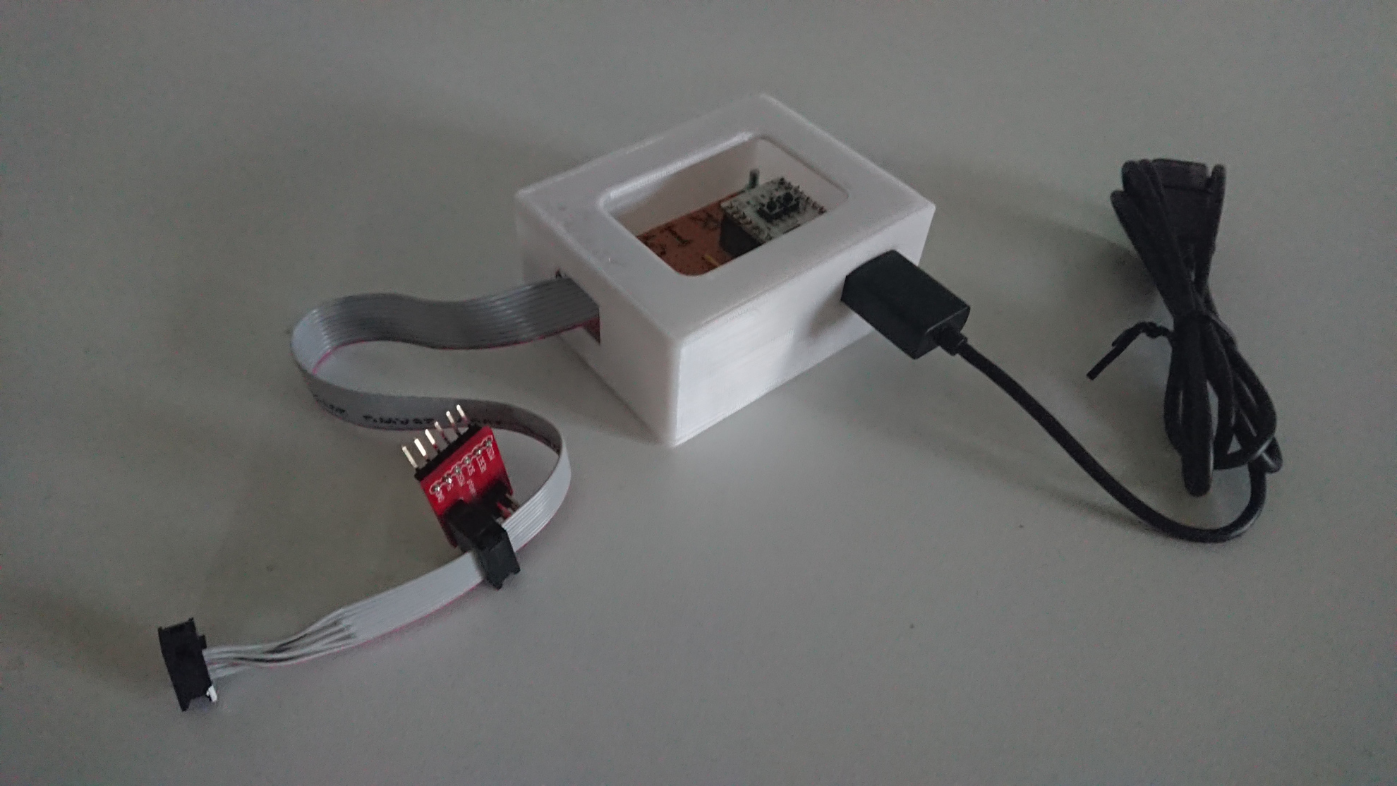
The tutorial says you can program the Arduino for this project using USB but I had problems doing that and found it easier to use an external programmer. This is my homemade AVR ISP Mk II programmer.
I made a little adaptor board for the programmer, using a cheap ZIF (Zero Insertion Force) socket on some veroboard.
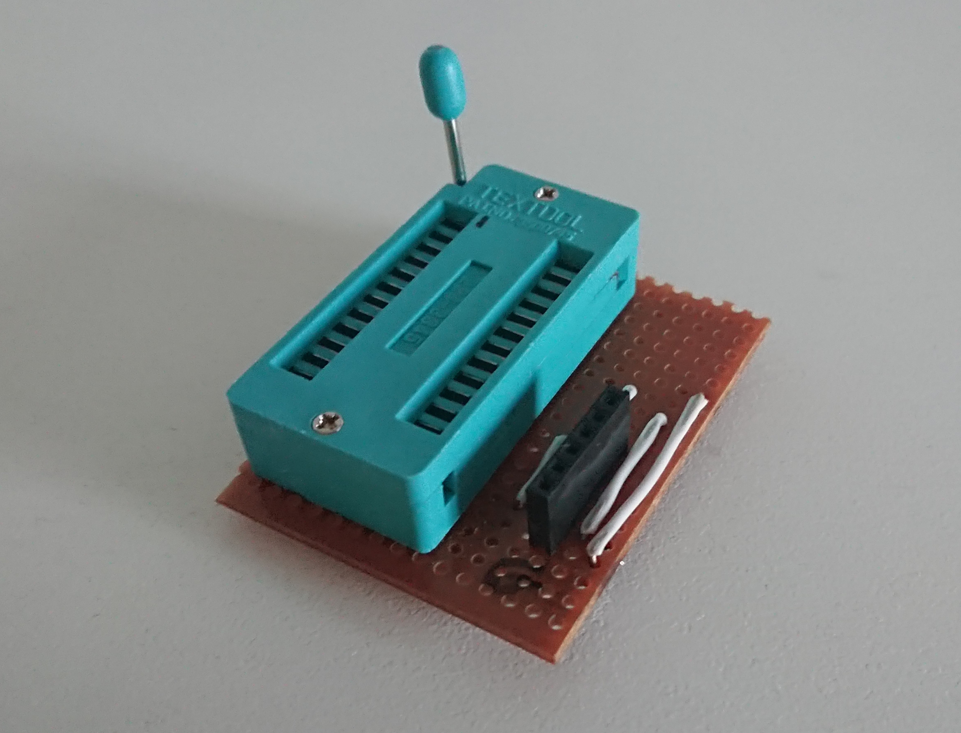
This isn’t strictly necessary for this project - First time round, I improvised with a breadboard and some jumper wires.
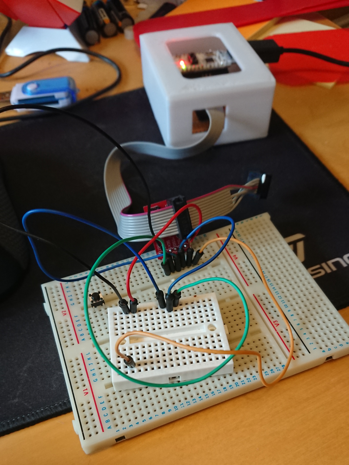
I had to cut and strip custom lengths of wire and solder it all by hand. This can be time consuming, but on balance, is probably less hassle than soldering connectors onto all of the wires and having to allow extra space in the case for them. I deliberately designed the controller so that all wires would be connected to a single piece of the controller, rather than, for example, having wires running from a controller on the lid to buttons on the side of the case.
The USB cable for the Mixbox connects directly to the Arduino through a hole in the rear of the case. It seems like a reasonably ergonomic arrangement in use, although the cable would be easier to insert if the Arduino were closer to the edge of the case. I don’t really like USB Type B Micro connectors as they do not have much mechanical strength. For this project I didn’t have room to add my preferred Type A socket, so have made do with the Type B connector on the Arduino board, packing it with hot glue for some extra support.
The small size of the controller means that it is sturdy, without the top plate flex of the larger Hit Box prototype that I made. I’d prefer slightly less travel on the buttons, particularly on the right hand action side of the controller. However, it is fun to use in game.
Some changes I will consider if I make a future version:
- Increase the case angle even more.
- Change the pin order for the direction buttons to make the wiring resemble the neater action button wiring.
- Mount the Arduino closer to the edge of the case so that the USB connector is more accessible.
- Add mounting supports for the Arduino.
- Make a lid that fits over the controller and clips on somehow.
- Print A, B, X, Y and arrow symbols on the buttons.
- Remove my name and share the files!