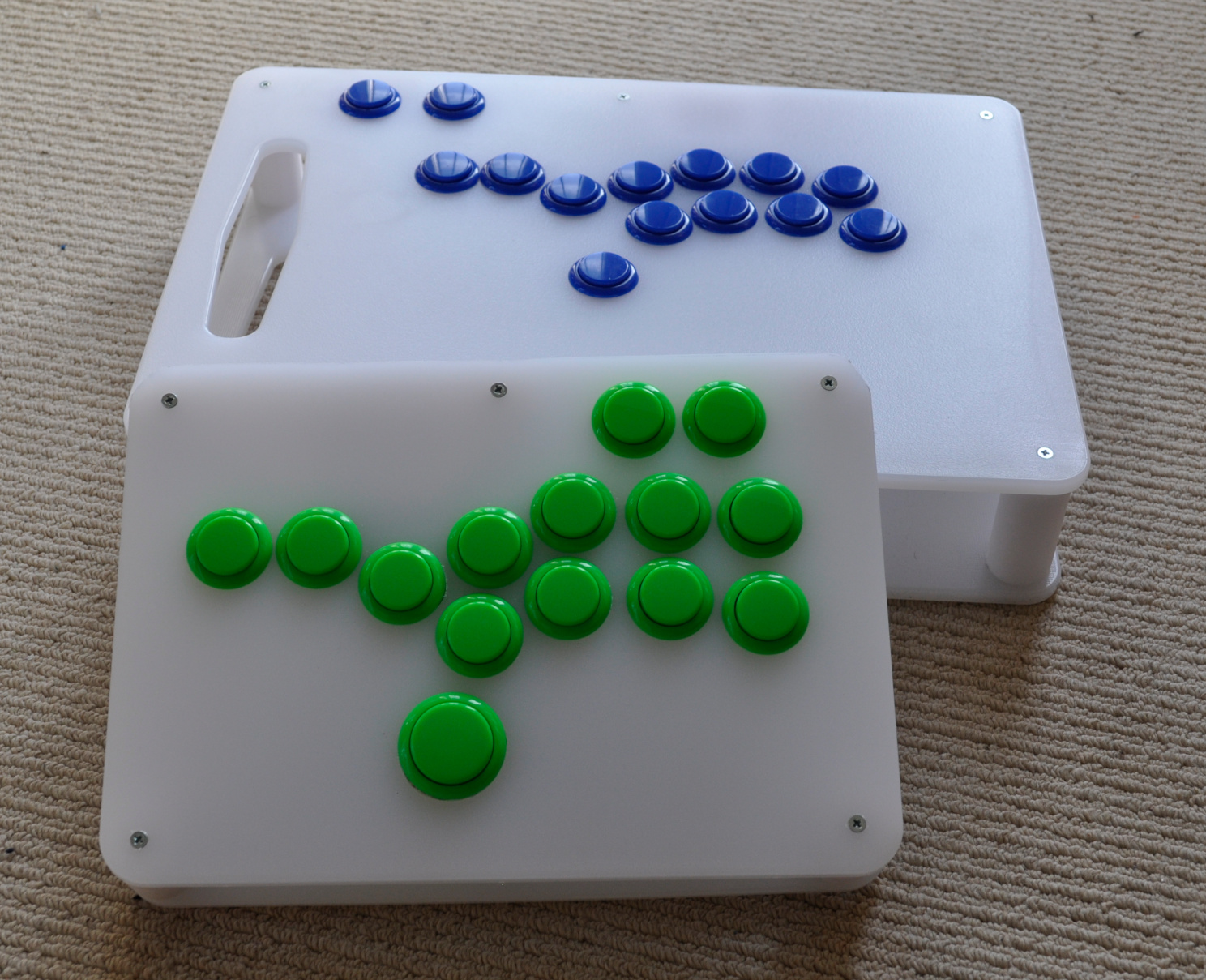
Chopbox Junior
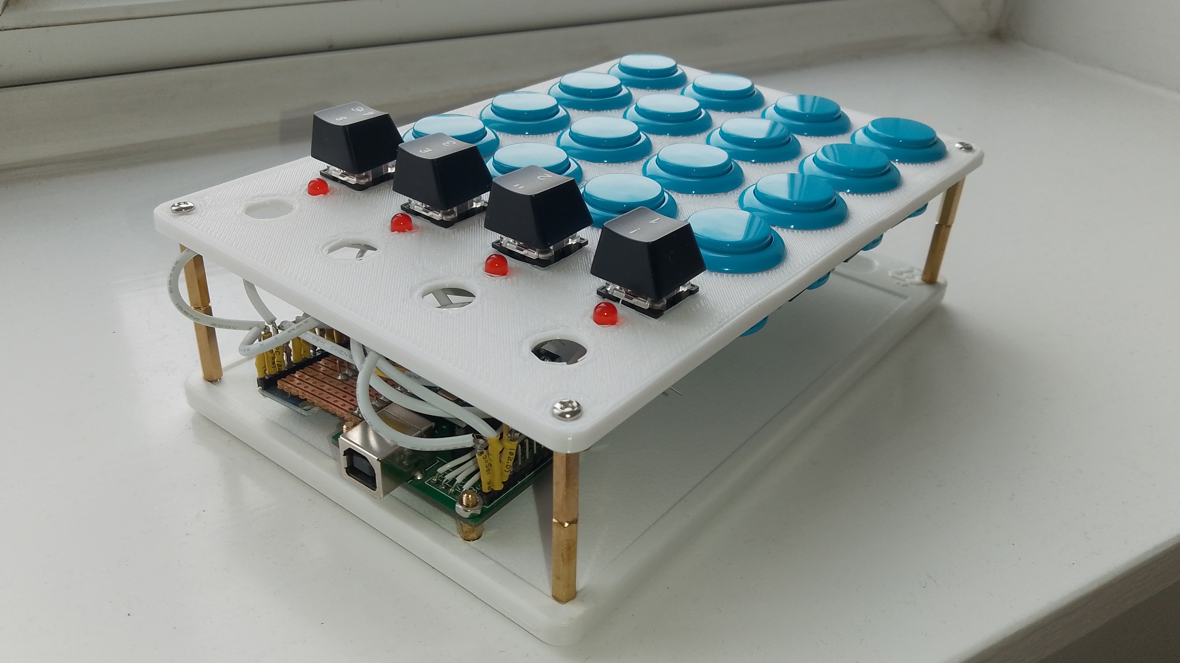
This is my latest project, The Chopbox Junior
This project is another evolution of my Tesco Chop Box. This time getting smaller. It is (almost - see below) the exact same software, hardware and case design, but using a half-sized board. If you want more info on how the electronics work, and how the case is designed, there is a much better guide in that article.
I was inspired to make this project after seeing the Junk Food Arcades Snack Box Micro. Mine’s not quite as thin as theirs but it’s also not Sold Out, and not $200, or whatever theirs costs when it is in stock. Plus mine has the benefit of using real Sanwa buttons, rather than keyboard keyswitch buttons.
Interestingly, I couldn’t help but notice that the Snack Box controller designs look a lot like my Chopbox designs. I hadn’t seen theirs when I made my first Chopbox, but I guess great minds think alike? It’s a pretty obvious way to cheaply and simply construct a nice solid controller.
My goal for this project was to produce a portable, smaller, thinner version of the Chopbox. I achieved the reduced depth by directly soldering the wires to the buttons, rather than using push-on connectors. I know I could get another few mm off the height but I didn’t want to compress the wires connecting to the Arduino.
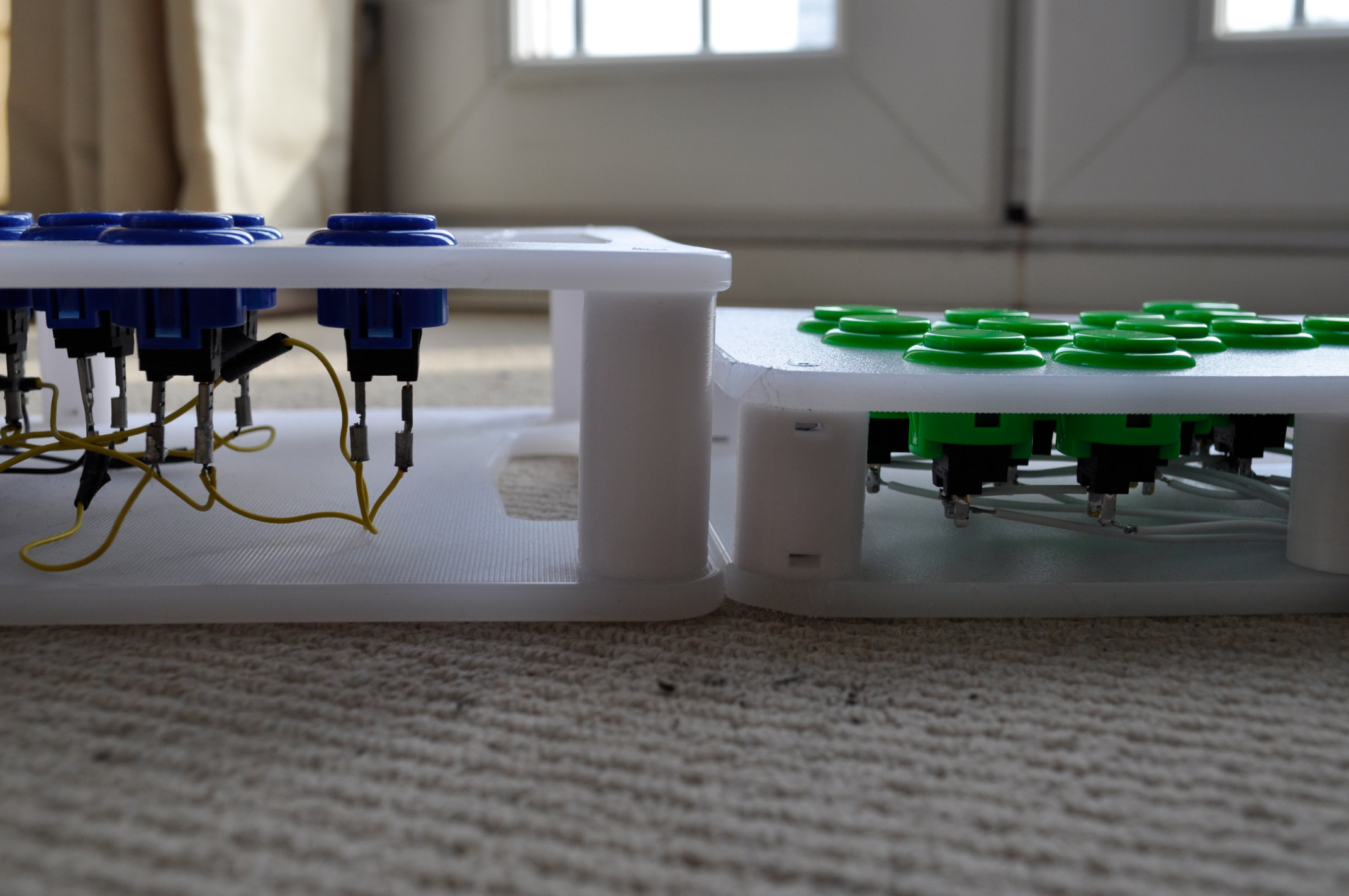
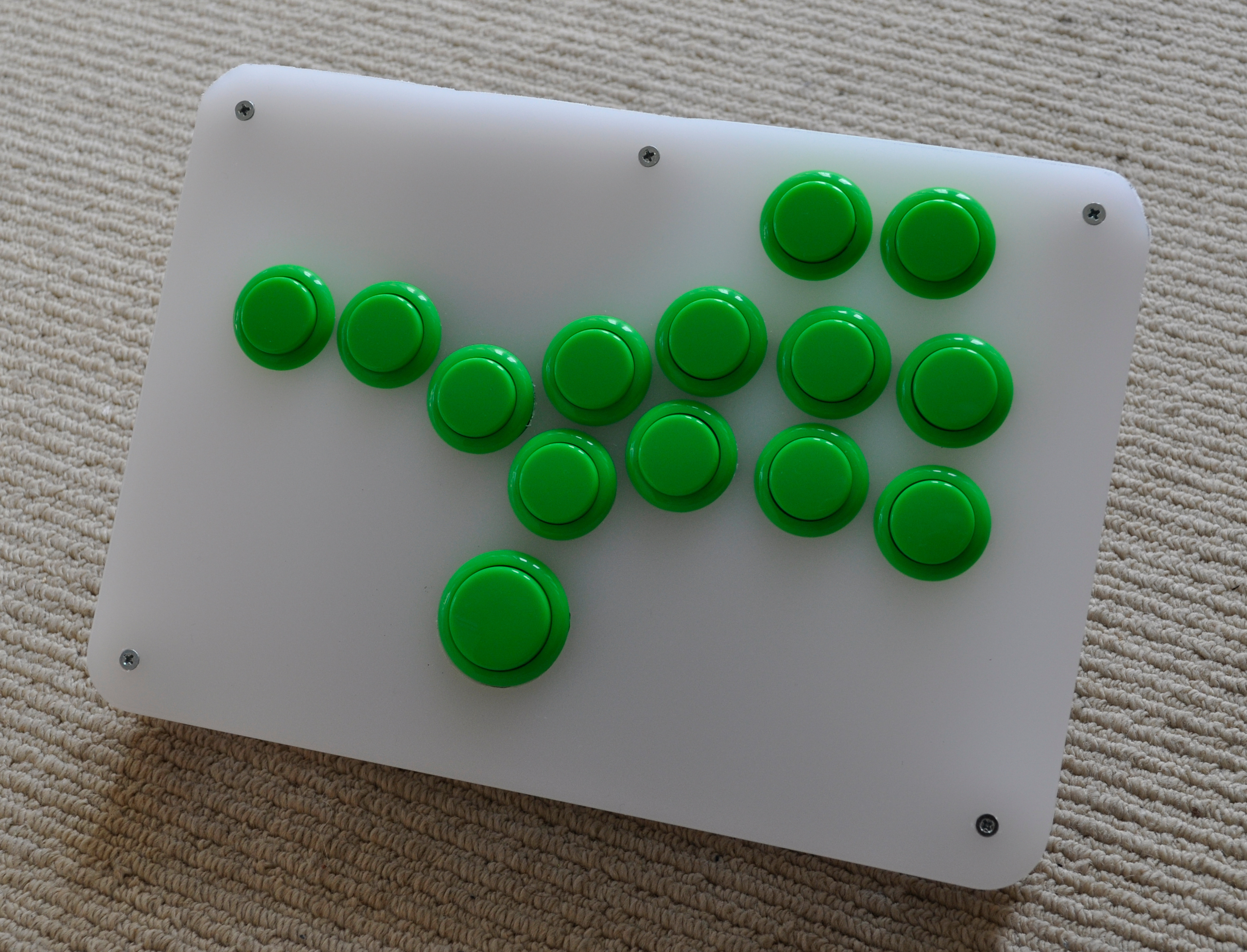
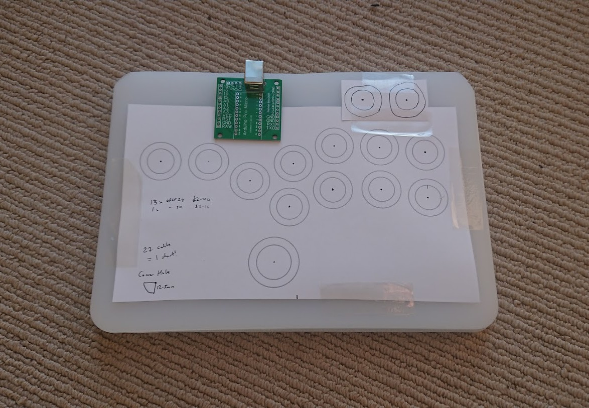
I also wanted to try out the standard Hitbox layout, rather than the slightly offset layout I created for the Chopbox. It turns out that I can’t really tell the difference when using it, although I do like the large 30mm thumb button. What does make a huge difference, though, is the lack of palm rest space. For this reason alone, I much prefer the original Chopbox.
Something else I managed to answer is the question of how well my DIY Arduino control board compares to the commercially available models, such as the popular Brook Fighting Boards.
Following the very well put together article on inputlag.science, I made an input lag tester.
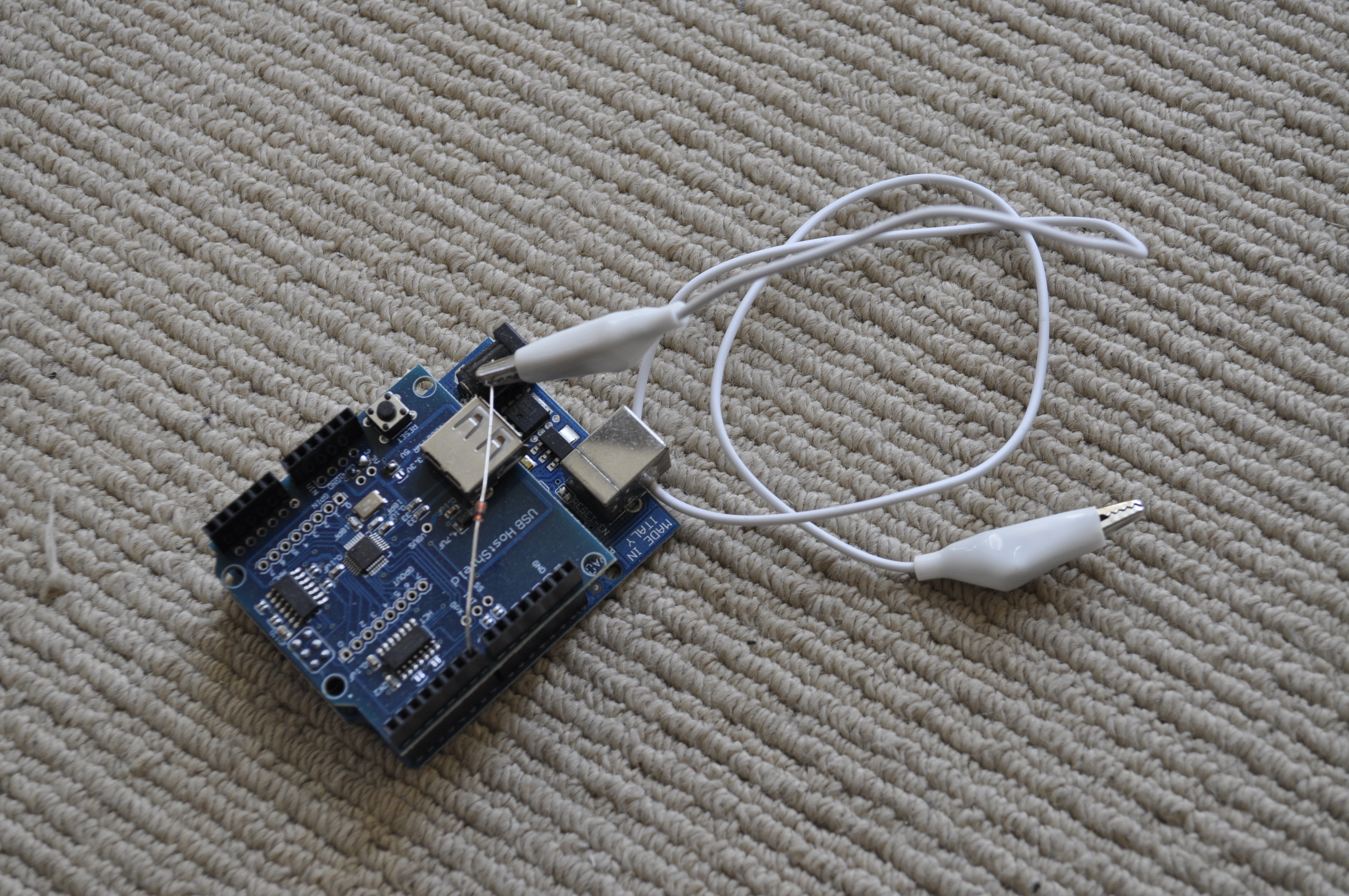
My controller came out OK compared to regular sticks (2.3ms /87% on time) but nowhere near the performance of the two top Brook boards. That won’t do!
I tried various investigations, including making a control board with the much faster STM32 Blue Pill board. Strangely this turned out a lot slower, so I suspect either something’s different with their USB implementation, or, more likely, I’m not configuring something correctly.
Eventually I discovered that the standard USB polling rate for XBox Controllers is 4ms, whereas the Brook boards are “overclocked” to 1ms. I changed my board to poll at 1ms, too, and now mine’s up there with the Brook boards in the results table.
I’ve not yet got round to upgrading my Chopbox to my new firmware, but since the controller board is removeable, it’s an easy upgrade that just requires me to unscrew the case bottom to get access to it. I think while I’m at it, I’ll re-drill the hole for the thumb button to take a 30mm button. Fortunately, I’ve got a spare one in the right colour.
Another difference in this project from the Chopbox is that I had some circuit boards printed at a Chinese PCB fabrication company. I had hoped this would make wiring easier but since the screw terminals I ordered didn’t arrive, I had to solder the wires to header pins, anyway. This was a tricky task, negating the whole point of making the boards which was so that I wouldn’t have to do this.
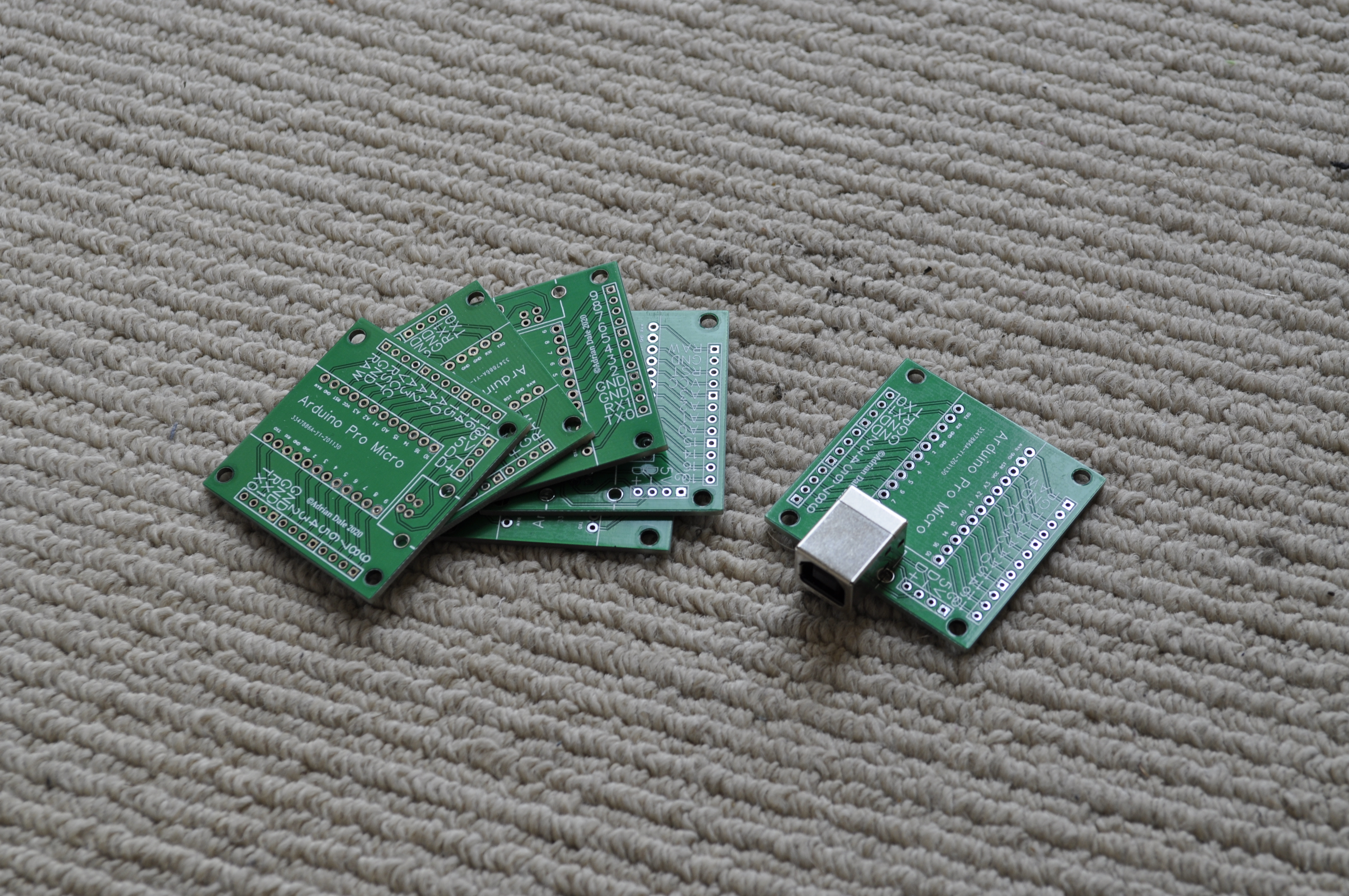
What it does help with, however, is in making the Arduino a lot easier to mount in the case, as it is now soldered to a PCB that has screw holes for mounting. I added a breakout board for a USB socket, too, as I hate the fragile USB micro type B connectors on the Arduino Pro Micro. Unfortunately there’s no way that I’ve found to avoid having to use the Pro Micro’s USB connector, so I had to make an cable to go from the Arduino to the breakout pins.
This is my revised board mounting post design. In the previous version there was only one post with the board on one side and the USB socket on the other. This meant that plugging the cable in could cause the post to rotate. In this new design, that can’t happen as the board is secured between the two posts.
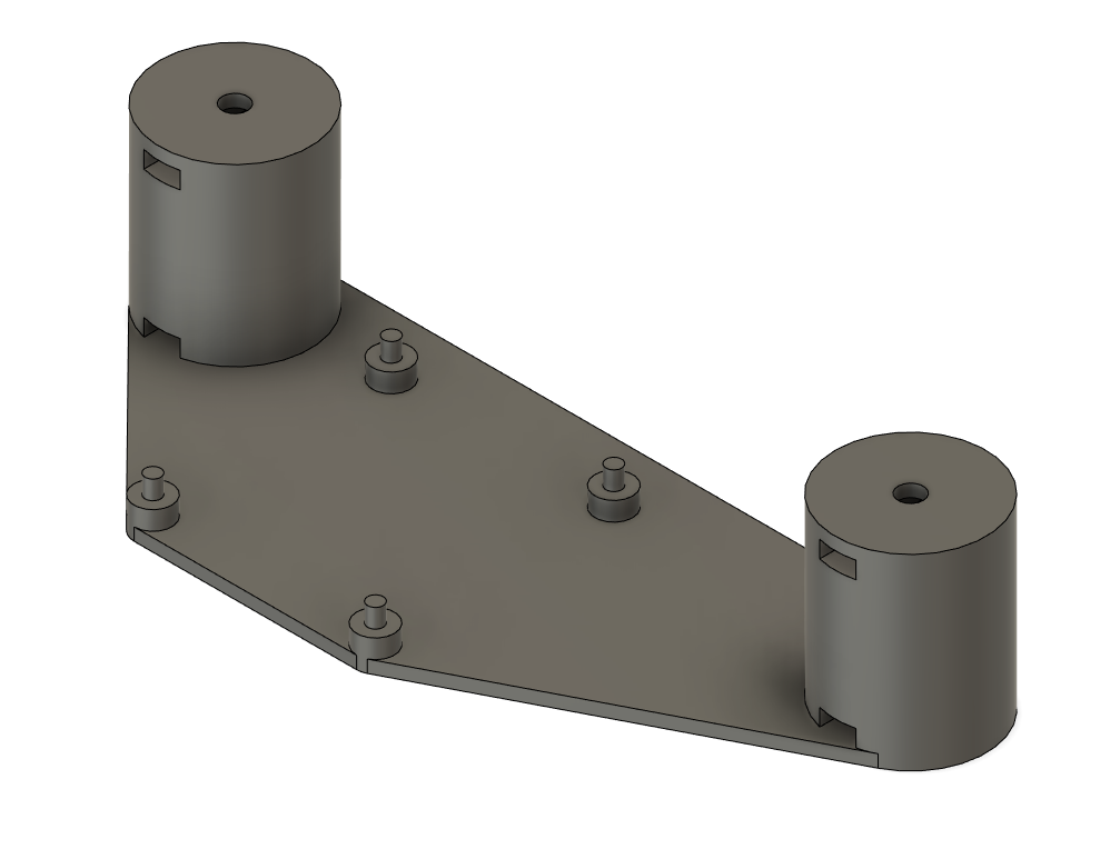
I think in a future project I may alter the captive nut design to have a slot on top of the post, instead of a screw hole. That way the posts will still fit even if I’m not 100% accurate drilling the holes in the top and bottom boards.
I’ve not shared the .STL files this time as they are very specific to this project and my custom boards. However, the mounting posts are pretty easy to design in a CAD or modelling package.